Pipe Conveyors
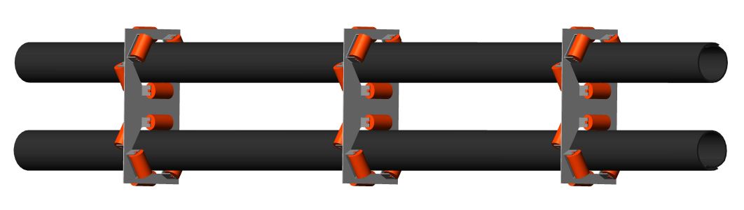
The Helix delta-T6 Conveyor Design program has the ability to design Pipe Conveyors. In a Pipe Conveyor, the belt is formed into a circular tube which fully encloses the conveyed material. The conveyor belt is an open trough under the loading chute and it is trained and formed into an enclosed tube for the length of the conveyor until it is once again opened to a troughed shape at the discharge pulley.
Download an example report of a Pipe Conveyor modeled in the Helix delta-T6 Conveyor Design Program: Demo 22 Existing PipeConveyor PC01 Coal 1000tph 4km Helix delta T6 Design Report.pdf
In Helix delta-T6 a Pipe Conveyor is denoted by selecting or inputting 6 Roll Idlers and a 360 degree Troughing Angle.
|
|
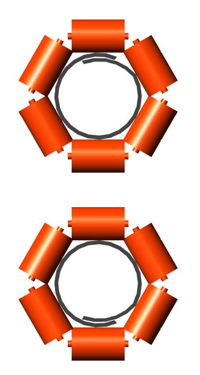
A typical Pipe Conveyor cross-sectional view. The belt is formed into a tubular shape by 6 idler rollers.
Summary of Pipe conveyor Advantages
- Conveyed Material is fully enclosed and weather protected
- Enclosing the conveyed material has environmental benefits with limited spillage
- Pipe Conveyors can generally navigate tighter (smaller radius) vertical and horizontal curves than conventional troughed conveyors
- Maximum Incline angle can be larger than for troughed conveyors, up to ~27 degrees for sluggish flowing material
- Material Surcharge Angle does not affect load capacity
Summary of Pipe conveyor Disadvantages
- Special Belt is required. The conveyor Belt must be designed for the Pipe Conveyor application and have correct transverse stiffness for the application
- A wider belt is required to transport the same capacity as a troughed conveyor
- The belt must be stiff enough to be self supporting in tube form
- The belt edge sections must be flexible in the transverse direction to allow for the overlap folding
- Steel cord belts must have transverse fabric layers to ensure sufficient self supporting stiffness
- Even / Constant Load Feed is required to prevent overloading
- Belt Thickness affects the load area of the tube
- Carry side belt resistance is normally higher than for a similar capacity troughed conveyor due to less load area availability and higher proportion of belt mass to material conveyor material mass. This results in a higher demand power.
- Return belt resistance is normally substantially higher than conventional troughed conveyors due to larger number of return belt rollers (rim drag is increased). This results in a higher demand power.
Calculation Methods
Helix Troughed Conveyor Calculation Method
- ISO 5048 (DIN 22101) Method
- CEMA method
- VISCO method - this method uses the rubber rheology properties to calculate the indentation resistance of the rubber belt on the conveyor idler rollers and also calculates the material and belt flexure losses, the idler rotation (rim drag) losses and the belt to idler scuffing losses. These four components make up the total resistance to movement of the conveyor belt. This VISCO method is also used to calculate conveyor resistance using Low Resistance Rubber (LRR).
The above methods have been successfully used to design many thousands of conventional troughed conveyors by Helix users in more than 30 countries.
The VISCO method is considered to be the most flexible and most accurate method of estimating the conveyor resistance because it allows the user to adjust multiple input values for different types of equipment which all affect the total conveyor resistance. For Example:
- The user can specify the belt top and bottom cover rubber properties.
- The user can specify the belt and material flexure factor.
- The user can specify the Idler Rotation Resistance.
- The user can specify the Idler Scuffing Resistance.
The above main resistances are all influenced by the load per m on the belt, the belt speed V, the idler spacing, the number of rollers, the idler roll diameter, belt top and bottom cover rubber properties (indentation hysteresis losses), the current belt tension which affects the amount of belt sag and resulting material and belt flexure losses, the accuracy of the idler vertical and horizontal alignment.
In the Helix delta-T program, the user can adjust all of these parameters and see the effects on the conveyor. A Sensitivity Analysis can be performed to arrive at an optimised conveyor design which will have the lowest total cost of ownership i.e capital, maintenance and operating cost.
Helix Pipe Conveyor Calculation Method
The resistance of a Pipe Conveyor may also be broken down into four main categories, namely:
- Belt to Idler Indentation Resistance
- Material and Belt Flexure losses
- Idler Rotation (Rim Drag) Resistances
- Belt to Idler scuffing losses
1. Belt to Idler Indentation Resistance
In a Pipe Conveyor, the folded belt adds additional load on the idler rolls imparted by the stiffness of the belt.
There are also more idler rollers (normally 6 for Pipe Conveyor vs 3 for a Troughed Conveyor) and more idler face length
is in contact with the belt.
The gravitational force resulting from the mass of the material and belt is taken on the three lower idlers, as it is in a
conventional troughed belt.
The upper two wing rollers and the top centre roller also have indentation losses due to the
folding of the stiff belt into a tubular shape.
There is also a resultant force on the lower three rollers due to the belt tension in a Convex vertical curve.
In a Concave vertical curve, there is a resultant force applied to the three upper rollers due the belt tension.
In addition, the wing rollers (the two on each side of tube) must also take the
resultant force due to the tensioned belt being curved around Horizontal curves.
The belt to idler indentation forces in a Pipe Conveyor may be summarised as follows:
- Belt Folding force - on 4 side rollers and top roller
- Gravitational Forces due to belt and material mass - on bottom centre and lower wing rollers
- Convex Curve Belt Deviation Load - on bottom centre and lower wing rollers
- Concave Curve Belt Deviation Load - on top centre and upper wing rollers
- Horizontal Curve Belt Deviation Load - on lower wing and upper wing rollers on inside of curve
In the Helix delta-T6 program, when you perform a Pipe Conveyor calculation, all of these individual indentation losses are calculated for each section of the conveyor and added to arrive an equivalent friction factor f for indentation resistance.
The user can see the resulting proportion of conveyor resistance attributed to Indentation, Flexure, Rolling Resistance and Belt Scuffing in the Viscoelastic Friction Factor Report.2. Material and Belt Flexure Resistance
In a Pipe Conveyor, as well as a Troughed Conveyor, the belt will tend to sag down to some extent
between supporting idlers under gravitational forces induced by the material and belt mass.
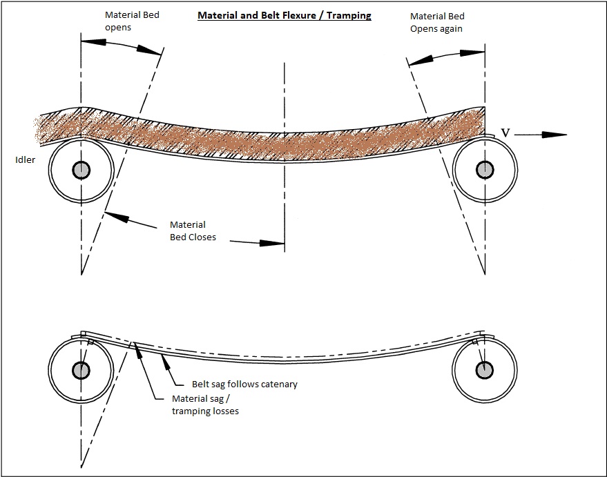
The pipe tube will also tend to bulge slightly between idler stations and there is a resulting resistance loss due the flexure of the material and belt as it deforms in travelling from one idler station to the next. The total material and belt flexure loss is a function of the belt tension, the amount of belt sag, the resistance of the material moving / shearing (internal co-efficient of friction of the material) and amount of belt flexure resistance due to its stiffness. Estimating this flexure loss is performed as described in the Belt and Material Flexure Calculation help topic in the Helix delta-T6 Program.
Adjusting the Material Flexure
To adjust the amount of resistance due to belt and material flexure you need to adjust the Material Flexure Adjustment Factor input value on the Viscoelastic Belt Properties Input Form. The default input value is set to 1.0 and this is the setting required for Iron Ore. You need to adjust this input value to reflect the relative internal co-efficient of friction of the material being transported. For example, if it is say dry Wheat, use a factor of 0.8 or even 0.7, and if the material is very hard, sharp angular ore or rock, use a value of say 1.1 or 1.2. The amount of flexure also depends on the amount of belt sag and also the troughing angle of the Idlers, the sag is calculated automatically and adjusted for each section.
3. Idler Rotation Resistance
In a Pipe Conveyor, as well as a Troughed Conveyor, the idler rollers have a resistance to rotation. The amount resistance depends on the manufacture of the idler, bearing and seal type. The actual value of the resistance can vary considerably from idler to idler and for a pipe conveyor, due to the higher number of idler rollers, this resistance can have a considerable effect on the total Pipe Conveyor resistance.
4. Idler Skew and Tilt Resistance
If the idler rolls are not aligned perpendicular to the belt travel direction, a scuffing resistance results. The magnitude of this scuffing resistance depends on the amount of misalignment as well as the co-efficient of friction between the belt and idler roll. The co-efficient of friction will in turn depend on whether the belt surface is dry, wet or moist.
Pipe Conveyor Friction Factor
The conveyor resistances for each section of the conveyor are calculated using the methods shown in the Viscoelastic
calculation method as described above. The four main resistance components (Indentation, Flexure, Idler Rotation and
Skew and Tilt resistance) are then added to give a total resistance R for each section
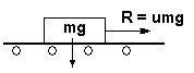
of conveyor. This total section resistance in Newtons is then used to back calculate the Friction factor μ because
the masses and idler loads m are known.
Pipe Conveyor Friction Factor Report
The following report shows the values of each component of the conveyor resistances.
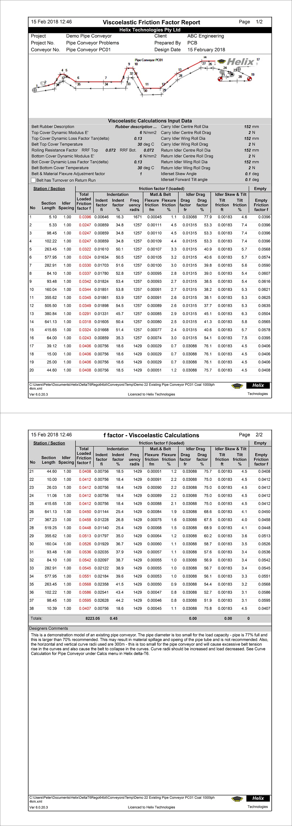
You can see from the above report that in the carry sections of the Pipe Conveyor, the total friction
factor varies in sections with no horizontal curves and increases in the curved sections.
(increases from 0.0247 in section 4 with no horizontal curve to 0.0322 in section 5 with 300m radius horizontal curve)
On the return belt sections from 26 onwards, the friction factor is higher than carry sections at about 0.045 to 0.056;
However, this does not mean the section resistance is higher in the return run because the mass is much lower as
there is no material being transported.
Resistance R is lower on the return belt even though μ is higher because m is much lower.
Proportions of Indentation, Flexure, Idler Drag and Idler Skew (Scuffing) Losses
In the report shown above you can see the proportions of the resistances as a percentage of the total for
each section:
Carry side (Section 11)
- Indentation loss is about 53.9%
- Flexure loss is about 2.6%
- Idler Drag loss is about 38.1%
- Idler Skew loss is about 5.3%
- Total μ = 0.0345
- Indentation loss is about 35.0%
- Flexure loss is about 1.2%
- Idler Drag loss is about 60.2%
- Idler Skew loss is about 3.6%
- Total μ = 0.0513
Indentation losses are lower on the return run than the carry side due to no material mass. The proportions of each resistance component can vary widely depending on the belt rubber properties, belt speed, idler spacing and idler rim drag. The designer should explore different settings to get an optimal design.
Steps for Design of a Pipe Conveyor
In Helix delta-T6 a Pipe Conveyor is denoted by selecting or inputting 6 Roll Idlers and a 360 degree Troughing Angle.
-
Build the model of the conveyor in the normal way as described in the Getting Started help topic in the Helix delta-T6 Program.
- In the Input, Input Carry Idlers form, select a suitable Pipe Conveyor Idler and ensure the Number of Rolls is set to Six (6)
- In the Input, Input Return Idlers form, select a suitable Pipe Conveyor Idler and ensure the Number of Rolls is set to Six (6)
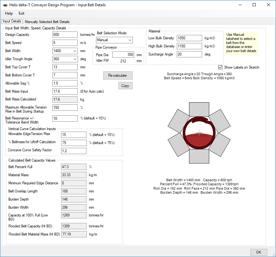
- In the Input Belt Details form you need to select a Belt Width and the corresponding recommended Pipe Diameter of Belt Width / 4 will be displayed
- In the Idler Trough Angle dropdown, select the 360 degree option
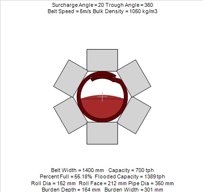
- The belt and tube cross-section will be drawn and the percentage full etc. calculated for you
- Now you can go to the Input Carry Idlers form, press the Open Idler Database button and select a suitable idler from the Helix Pipe Conveyor idlers category. Choose an idler for the Belt Width and Pipe Diameter you have input in Belt Details.
- The Pipe Conveyor Idlers which are in the Helix delta-T Idler Database are presented as a design guide only. The Pipe Conveyor Idler database is derived from the Sandvik Carry idler data with the Idler Face width, Bearing Centres and Support Centre dimensions adjusted to suit the selected Pipe Diameter. These specific idler dimensions are theorectical only, designers must obtain real idler data from their own manufacturer for final design.
- Repeat the pipe conveyor Idler Selection process described above for the Return Idlers
- The Number of Idler Rolls must be six (6) for a Pipe Conveyor
- Now return to the to Belt Input Details form and the Belt Cross-section will be redrawn with the selected Idlers and Belt Width
- The cross-section above shows the percentage full and belt overlap length as well as the chosen idlers. Note the idler rolls overlap each other slightly in this diagram, these are staggered idler panels with Offset idlers
- Ensure the conveyor material low and high bulk density are correct, adjust if necessary
- Adjust the belt speed to yield a pipe percentage full of less than 70% for fine material or less than say 60% full for material with large lumps. The Maximum Belt speed will depend on the Idler Load and Bearing life and should be adjusted to give an idler rotation speed of less than 600 rpm.
- There are no known published maximum belt speed limits for Pipe Conveyors, but as for Troughed conveyors, a speed higher than about 5.0m/s is considered an upper limit, especially with 152mm diameter rollers. Belt Speeds exceeding 5.0m/s may result in resonance problems, material shifting in the pipe tube which can cause material bunching and force the belt to open and spill material. There are many factors which can affect the Belt Resonance / Material Bunching phenomenon such as belt tension, belt sag, idler spacing, idler roll diameter, idler rotation speed (belt seed) and caution should be exercised in selecting a reasonable belt speed which is not too high. Details and videos of Belt Resonance and Material bunching are shown in the Helix website at Helix Conveyor Design - Belt Resonance
- Complete all Input Values in all the other forms in the main form Input Menu including the Takeup, Drive and Motor Inputs etc.
- You also need to complete all the Viscoelastic Belt Input Details and the Viscoelastic Idler Input Details.
- Once all Input values have been completed, you can do the conveyor calculation using the VISCO method. Pipe Conveyor calculations must be performed using the VISCO method. The ISO and CEMA methods will not yield correct belt tensions and power for a Pipe Conveyor, but are included for comparison purposes only.
- Once you have completed all inputs and the VISCO calculation method, you can view all the results by using the Reports menu
- The next step for Pipe Conveyors is to check the suitability of the Vertical and Horizontal curve radii. Use the Horizontal Curve Calculations help topic in the Helix delta-T6 Program for further explanation.
Summary of Design Guidelines for Pipe Conveyors
Pipe Conveyors have some additional features compared to conventional troughed conveyors, i.e the belt has to be formed into a tube after the loading point and it also has to be opened from tube to flat at the discharge pulley. These sections of the belt are called transitions; they are similar to the Trough Transition in a conventional Troughed belt conveyor, except that the edge length (hypotenuse) is longer as the belt goes from flat at the pulley to more than 360 degrees of closure.
- Conveyor Belt must be designed for the Pipe Conveyor application and have correct transverse stiffness for the application
- Belts can be Fabric or Steel cord reinforced
- The belt must be stiff enough to be self supporting in tube form
- The belt edge sections must be flexible in the transverse direction to allow for the overlap folding
- Steel cord belts have transverse fabric layers to ensure sufficient self supporting stiffness
- Pipe Diameter (D) = Belt width / 4
- A Larger Pipe Diameter requires an increased belt transverse stiffness to maintain the tubular shape
- A Smaller Pipe Diameter requires less belt transverse stiffness to maintain the tubular shape than a larger diameter pipe
- Maximum lump size = 25% to 33% of Pipe Diameter (use lower % for high proportion of lumps)
- Maximum Loading = < 70% of load area for small lumps
- Maximum Loading = < 60% of load area for larger lumps
- Material Surcharge Angle does not affect load capacity
- Belt Thickness affects the load area of the tube
- Even / Constant Load Feed is required to prevent overloading
- Idler Trough Angle must be set to 360 degrees for Pipe Conveyor
- The No. of Idler Rolls must be six (6) for a Pipe Conveyor
- Maximum Incline angle can be larger than for troughed conveyors, up to ~27 degrees for sluggish flowing material
- Maximum Recommended Idler rotation speed is 600 - 750 rpm
- Tube Fold Transition Length: Allow at least 25 to 40 x D for Folding and unfolding belt for Fabric belts (use larger value for large Pipe Dia)
- Tube Fold Transition Length: Allow at least 40 to 50 x D for Folding and unfolding belt for Steel belts (use larger value for large Pipe Dia)
- Carry side belt resistance is normally higher than for a similar capacity troughed conveyor due to less load area availability and higher proportion of belt mass to material conveyor material mass
- Return belt resistance is normally substantially higher than conventional troughed conveyors due to larger number of return belt rollers (rim drag is increased)
- The VISCO calculation method must be used Pipe Conveyors
- Check the minimum Curve Radius required for a each curve in Pipe Conveyor. Refer to the Horizontal Curve Calculations help topic for an explanation.
The required minimum length of the transition is governed by limiting the edge tension rise and also limiting the center tension drop which results for the edges being stretched.
Pipe Conveyors - Horizontal and Vertical Curve Calculations
Pipe Conveyor Curves
|
|
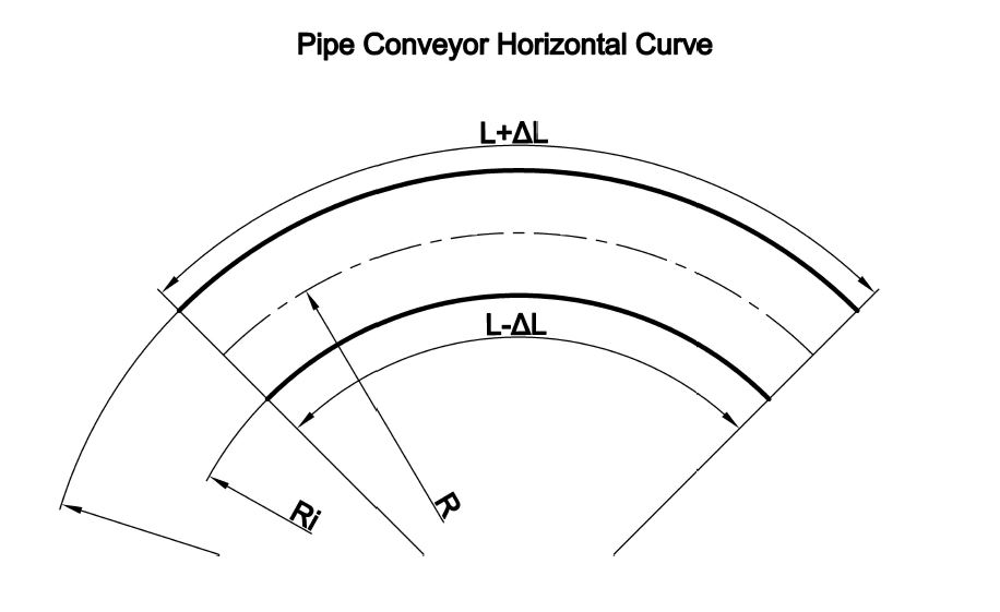
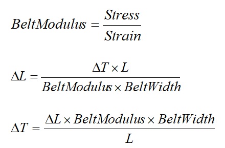
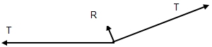
In a Pipe Conveyor curve, the portion of the belt furthest away from the centre of the curve is stretched while the portion or half of the belt on the inside of the curve is compressed into a shorter length. The belt is under tension and the change in tension Δ delta T is added to the outside portion of the belt and a corresponding reduction in tension is applied to inside portion of the belt because the average tension across the belt width remains a constant.
We need to ensure that the rise in tension does not exceed the working tension of the belt and also ensure that the reduction in tension on the inside does not force the belt into compression because it will buckle.
The Pipe Conveyor Curve Calculations must be performed for each Vertical and Horizontal curve in the pipe conveyor.
Design of curves for a Pipe Conveyor
One the main advantages of Pipe Conveyors is that they can negotiate relatively small radius Horizontal curves when compared to conventional Troughed conveyors. Each vertical and horizontal curve in a Pipe Conveyor needs to be checked for:
- Belt Tube Outside belt tension rise - too high a tension will over-stress the belt
- Belt Tube Inside belt tension fall - too low a tension will make the belt go into compression and cause tube and belt buckling
-
Concave Vertical curves must have sufficient radius to ensure that the belt does not tend to lift off the lower idlers and
cause the tube to be compressed against the upper idler rollers. The belt lift is caused by the belt tension resultant force from
the change in vertical angle. This calculation is the same as for a Troughed conveyor.
- Concave and Convex vertical curves have a Belt Tube Outside (upper half) belt tension rise - too high a tension will over-stress the belt
- Concave and Convex vertical curves have a Belt Tube Inside (lower half) belt tension fall - too low a tension will make the belt go into compression and cause tube and belt buckling
The required minimum concave curve radius for belt lift off for Item no. 3 above is calculated as it is for Troughed conveyors
and is shown in the Vertical Curves Report.
For each Concave and Convex vertical curve and each Horizontal Curve in a Pipe a Conveyor, the Calculate Pipe Conveyor Curve calculation under the main form Calcs menu must be used to check for high and low tensions in the curve. Refer to the Calcs menu shown below.
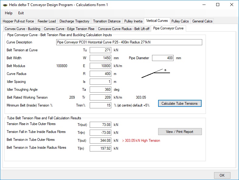
- Enter the input values for the curve under consideration. You can enter a Curve Description which shows the location of each curve so that this description can be used to identify which curve has been calculated.
- Enter the Belt Width and Pipe Diameter in mm
- Enter the Belt Modulus, Curve Radius and Idler Spacing
- Enter the Trough Angle. It must be 360 degrees for a pipe conveyor
- Enter the Belt Rated Working Tension in kN/m width
- Enter the Minimum Tension as a percentage of Rated Tension. Default value is 5% minimum belt tension, less than this may result in belt buckling due to the belt going into compression
- Press the Calculate Tube Tensions button
- The program will calculate the rise in tension in the outer half of the belt. The belt is stretched through a further distance in the outside of the curve and travels through a shorter distance in the inside of the curve.
Pipe Conveyor Curve Calculation Report - Tension too low
After doing the Pipe Conveyor Curve Calculation as described above, you can View and Print a report for each curve in the Pipe Conveyor
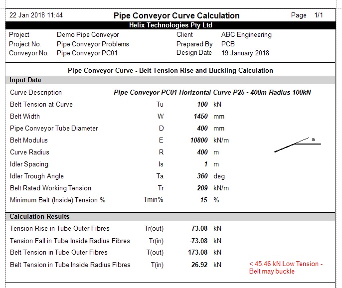
Tension at inside of curve is below the minimum required tension of 15% of belt rated tension. (The 15% value is a design input value, a minimum of at least 5% is recommended)
Pipe Conveyor Curve Calculation Form - Tension too high
Tension at outside of curve is above the rated tension of the belt.