HELIX delta-T6 - Feeder Calculation - Theoretical Method 
You can calculate the additional forces required to pull material out of a hopper or bin. Select the Calcs, Calculate Feeder Loads menu from the main form. The following form will be displayed:
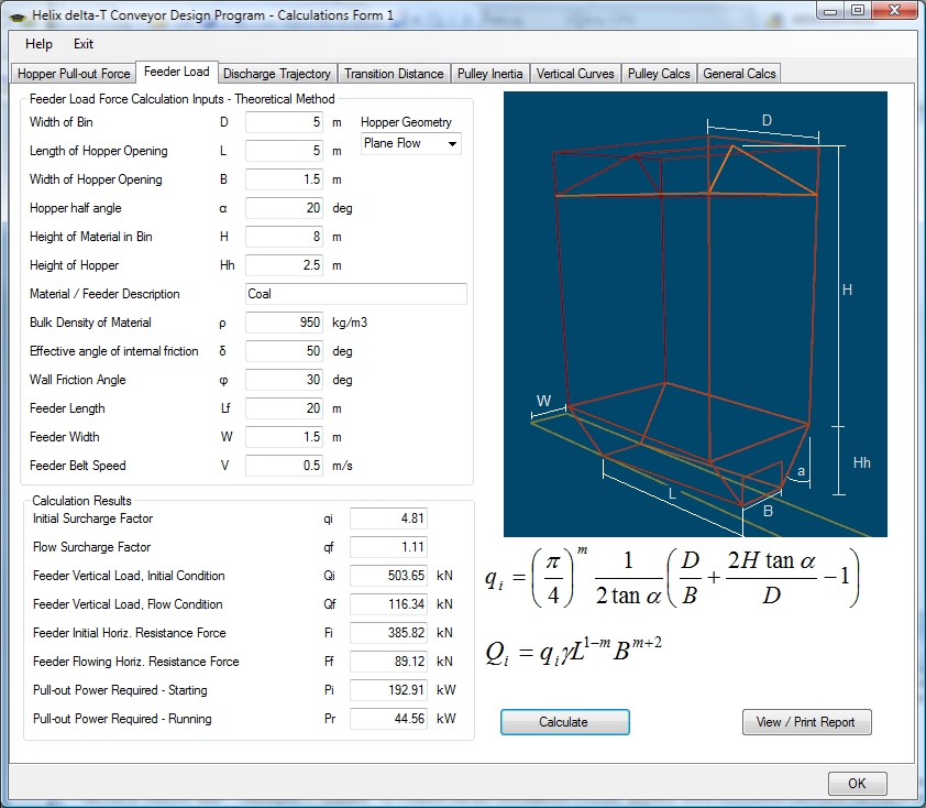
This form allows you to calculate the Additional Tension required to pull a material out of a feeder, bin or hopper. This additional tension is mainly due to the shearing action required to pull the material out of the hopper opening. The method used here is the 'Theoretical' method developed first by arnold and McLean and the then refined by A.W. Roberts and others. Many papers have been published on this subject and some are quite complex, however, Helix have refined the inputs to those shown in this form. The material in the feeder will require testing in order to determine the wall frcition and effective angle of internal friction.
The initial surcharge factor qi is calculated and then the feeder vertical load is calculated using qi, see formula shown on form.
Alternatively, two other emperical methods of calculation are offered - Bruff's method and the method proposed in the Bridgestone conveyor design manual, see the Calcs, Calculate Pull-out Force from Hopper menu.
Input your feeder and material data and then once you have obtained the feeder vertical and horizontal pull out loads you can use the method shown below to model the belt feeder conveyor.
Once you have the magnitude of these Pullout force tensions, you should design the Feeder as a normal conveyor and add the Pullout Tension as a Tension Adjustment in the Input Sections form.
You will note that two Tensions are given:
- Starting or Initial Pull-out force
- Running or Flow conditions Pullout force
The higher Starting force is required to overcome the interlocking (or bridging) of the material whilst stationary. Once it is flowing, the force required reduces.
HELIX delta-T6 - Feeder Calculation - Bruff's Method
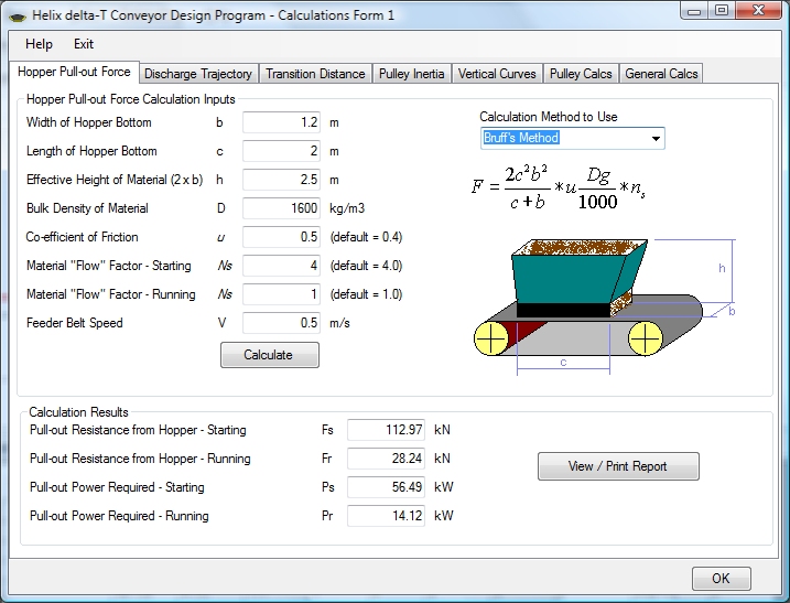
This form allows you to calculate the Additional Tension required to pull a material out of a hopper. This additional tension is mainly due to the shearing action required to pull the material out of the hopper opening. The methods shown and used are quick estimation methods and it must be pointed out that the design of feeders and calculating the loads is a complex subject and requires testing of the material properties which is beyond the scope of this program. The methods shown here do not require any testing or special material properties and are provided as an estimate of loads.
Once you have the magnitude of these Pullout force tensions, you should design the Feeder as a normal conveyor and add the Pullout Tension as a Tension Adjustment in the Input Sections form.
Two methods of calculation are offered - Bruff's method and the method proposed in the Bridgestone conveyor design manual. Generally, Bruff's method is more conservative and is the preferred choice for safety. The Bridgestone method is more conservative when the depth of material in the hopper is large.
You will note that two Tensions are given:
- Starting or Initial Pull-out force
- Running or Flow conditions Pullout force
Belt Feeder Calculation Procedure in Helix delta-T6
- Build a model of the conveyor
- Go to Calcs, Feeder Calculations and enter the hopper dimensions and material properties
- Press Calculate
- Transfer the Feeder Flowing Horizontal Resistance Force Ff to the Conveyor Sections, Tension Adjustment column.
- Re-calculate the Conveyor using ISO, CEMA or VISCO buttons
- The Tension Adjustment will have been added to the conveyor model - details can be seen in the Tension Calculation Reports
- Note the conveyor absorbed and installed power and the Starting Torque Factor which depends on starting method and motor.
Now you should substitute the Running Pullout Tension with the Starting Pullout Tension in the Tension adjustment and re-calculate the conveyor. If the absorbed power is less than the Installed Power x Starting Torque factor then there is sufficient power and torque to start the conveyor. A numeric example is shown below:
Conveyor Speed = 1.0m/s, belt power = Te x Belt Speed.
Effective Tension (3kN) and Absorbed power without Tension Adjustment = 3kW say.
Calculate hopper and add a Running Tension adjustment of 2kN say. Te is now 5kN and absorbed power 5kW. Installed power is selected as 7.5kW motor started Direct on Line with starting torque factor of 200% FLT.
The Starting Tension adjustment is (say) 4 x Running = 8kN say. So for starting the Te becomes 3 + 8 = 11kN or 11kW and we have available 7.5kW x 200% = 15kW so it is OK.
After Calculations are done you can view, Print or Export the report.
The following references are shown if you would like to research these methods further.
References
- McClean A.G, Arnold P.C, 'A simplified approach for the evaluation of feeder loads for mass flow bins', Powder & Bulks Solids Technology Vol.3 No.3
- A.W Roberts et.al, 'Wall Pressure-Feeder Load Interactions in Mass Flow Hopper/Feeder Combinations', Bulk Solids Handling Vol 6 No.4
- A. E Maton, 'Belt Feeder Design: Starting Load Calculations', Bulk Solids Handling 8 2009