 HELIX delta-Q2 Pipe Network Analysis Slurry Calculations
Delta-Q2 can model Heterogeneous settling slurries with Newtonian fluid properties and also non-Newtonian Homogenous Slurries such as Bingham Plastic type Slurries.
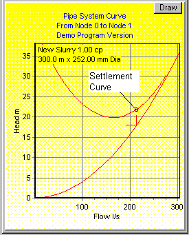
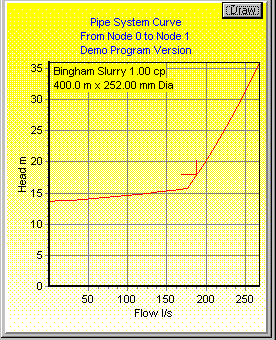
| Heterogeneous (Settling) Slurry | Homogenous non-newtonian slurry |
|---|---|
 |
 |
| Settling Slurry System Curve showing duty point below optimum flow rate to prevent settling. | Homogenous Slurry System curve showing laminar and Turbulent flow regions. You can model Bingham and pseudoplastic slurries using delta-Q. |
Features of the Helix delta-Q program relating to Slurries
- Design and Solve Complex Slurry Pipe System Networks.
- Model Slurry Transport, Plant Slurry Systems, Mill Circuits, CCD Thickener Systems, Tailings Disposal, Mine Backfill, Process Solution Systems, Lime Neutralisation Systems with ease.
- The program can model Heterogeneous settling slurries with Newtonian fluid properties and also non-Newtonian Homogenous and Bingham Plastic type Slurries.
- The program uses a minimum of slurry input data for each type of slurry. Rheological data is required for non-Newtonian slurries.
- Calculates Settling Velocity for Heterogeneous slurries and Critical Velocity for Non-Newtonian Bingham type Slurries.
- The program produces warnings if low flow velocities will result in slurry particle settlement. For Non-Newtonian slurries, if shear rates are too low to produce flow, a blocked pipe condition is simulated in the network with an accompanying warning flag.
- Pump Performance Correction factors are calculated by the program depending on slurry particle size, concentration by volume and particle SG.
- Pipe System curves are drawn showing system resistance curve, settling slurry resistance curve and flow duty point. For Bingham slurries, the laminar plug flow resistance curve is drawn This allows you to size each pipe correctly to ensure most economical operation and to avoid blocked pipe conditions.
- Drag and Drop Network components onto the screen for quick and easy network creation.
- Calculate Fitting Losses using the standard K value method or the Kf method which compensates for fluid viscosity and turbulence.
- Setup individual Fluids and properties in each pipe - Model real world process lows with different slurries in the same network. For example, you may have a concentrated slurry in one pipe flowing into a junction with a water pipe (or pipes) and dilute slurry flowing through the network from that point onwards.
- Include Networks with unknown pressure nodes and unknown flow nodes or any combination of the two.
- Model slurry networks containing any number of pumps, Hoppers, Tanks, junctions and outlet nozzles.
